Subject Preparation: EEG
EEG Reference Electrode Setup
Reference Electrodes / Mastoid Placement: Used to define the electronics common point.
- Left and Right Mastoid Placement - Bone prominence behind the ear.
- Clean the skin behind the left and right ear with alcohol and Nuprep Skin Cleaner. Wipe the skin to remove the gritty residue.
- Attach Large (EEG) Adhesive Washers to the electrodes.
- Press the electrodes onto the skin.
- Apply Elifix Electrolyte through the electrode opening.
- Check the impedances using the Grass Impedance Meter.
- Plug in the left mastoid electrode in jack 1 and the right mastoid electrode in electrode jack 2.
- Push the red ON button.
- The Electrode Selector should be at 1 or 2.
- Mastoid electrode Impedance should be less than or equal to 5K ohms.
- Refer to the section entitled “Electrode Impedance Meter Check” for more detailed information on reducing impedances.
- Secure with tape.
EEG Easy Cap System
The Easy Cap is a modular EEG-recording cap system with 64 ring adaptor locations using Ag/AgCl sintered electrodes. *Other application methods may be used, however, careful attention should be given to the choice of methods and electrode selection; refer to Electrode Criteria.
Measuring / Marking Frontal Polar, Cz & Occipital Locations
- Measure the nasion – inion distance. Place a mark at 50% of the total distant. This marks Cz.
- From the nasion place a horizontal mark at 10% of the nasion – inion distance. This marks FPz.
- Place a vertical mark on the forehead midline nasion. For accuracy measure the distance between the eyebrows; mark midway crossing the horizontal mark. This completes Fpz.
- From the inion place a horizontal mark at 10% of the nasion - inion distance. This marks Oz.
- Measure head circumference from the Fpz position. Place a vertical mark at 50% of the distance of the circumference. This completes Oz.
- Measure and mark 5% of the circumference distance on the left of FPz (on the same horizontal plane). This completes Fp1.
- Measure and mark 5% of the circumference distance on the right of FPz (on the same horizontal plane). This completes Fp2.
- Measure and mark 5% of the circumference distance on the left of Oz (on the same horizontal plane). This completes O1.
- Measure and mark 5% of the circumference distance on the right of Oz (on the same horizontal plane). This completes O2.
- Measure from left to right preauricular points across the top of the head. Mark the midpoint. This completes Cz.
Mounting The Cap
EasyCap Size Small Medium Large Head Circumference ≤ 56cm ≤ 58cm ≤ 60cm
- Select a cap size based upon the head circumference measurement.
- Rotate the adaptors in the cap so that the narrow opening is toward the back of the head.
- Place the Large (EEG) Anchoring Adhesive Washer on the inside of the cap on the adaptors at Fp1 & Fp2 locations.
- Press Fp1 & Fp2 with the attached adhesive washers onto the forehead at the marked locations.
- Have the subject hold Fp1 & Fp2 in place while turning the cap over the head.
- Gently pull the cap over the head and ears into place.
- Check and adjust the cap so that the Cz electrode is at the Cz mark.
- Check and adjust Fp1 & Fp2 and O1 & O2 to assure that they are placed correctly; if not, choose another cap size.
- Anchor the cap with the chest belt (or the chin strap).
- Snap the electrodes into the adaptors on the cap in a systematic manner starting at the back of the head. *This step isn’t necessary if the electrodes are already on the cap.
- Insert the electrodes so that the lead wire points toward the narrow side of the adaptor.
- Using an old ballpoint pen (or the fingers) where the mine (the point of the pen) has been removed push the electrode into the adaptor.
- Do not to bend or place excessive pressure on the lead wire where it attaches to the electrode.
Digitizing Electrode Positions
The Polhemus Digitizer is used for the digitization of the EEG electrode positions and for the determination of head shape. Digitize all electrode positions using the Polhemus.
1) After the Easy Cap has been placed on the subject, position the small Receiver Module on the back of the head on top of the cap near midline. Secure with tape.
2) Place the large Transmitter on a non-metallic stand midline directly behind the subject. Tape the transmitter to the stand to secure.
3) Turn on the laptop computer located on the portable cart.
4) Open the Polhemus Electrode Digitizing Program.
5) Double click on the Electrode Digitizer Program.
6) The software should detect two (2) stations: the receiver and transmitter.
7) If the software does not recognize both stations, check the connections then restart the program.
8) Click on Define Head Coordinates.
9) Define the head coordinates by placing the stylus pen tip at the center of a head coil location (nasion, left preauricular, right preauricular) then press the stylus button. If a mistake is made,
- - Press the stylus pen until all head coordinates have been entered then,
- - Press define Head Coordinates again. Do not save the previously acquired locations simply start over from the beginning.
10) Click on Digitizing Start / Stop.
11) Place the stylus pen at the center of an electrode location as designated by the digitizing program then press the stylus button.
- - A single data point is collected each time the stylus button is depressed and a beep will alert the user to each acquired point.
- - The program will assign a number to the electrode position in the sequence the electrodes are selected, i.e., 1, 2, 3, 4, etc.
- - If a mistake is made, click on Remove Last Point and try that position again.
- - Click on Digitizing Start /Stop when all electrode locations have been done.
12) At the end the program a head diagram will appear on the screen.
- If the diagram is:
- - Correct then continue with Step 13.
- - Not correct then check to make sure that the receiver or transmitter did not move then repeat digitization (steps 5-11).
13) Click on File / Save Data.
14) Save the data to the hard drive and
15) Save to a floppy disk.
16) The filename is the current date.
17) Exit the program. Eject disk. Turn off laptop.
18) Transfer the Polhemus head coordinate file from the disk to the computer at the acquisition workstation / console.
Note: The operator and anyone within 10 feet of the transmitter and receiver should de-metal. The general rule of thumb is three times the separation distance between the transmitter and receiver from any metal in the room. For example, if the separation distance is one foot, metal within three feet of the transmitter or receiver may cause distortion and inaccurate measurements.
Reducing Skin Impedances
Lemon Prep or Nuprep can be used for reducing skin impedance. Both are topical abrasives used to clean the skin to remove any natural or applied oil, lotions and/or dead skin. Remove with water.
- Insert the wooden end of a cotton swab through the opening of the electrode to push hair aside (in one direction) until the skin is clearly visible.
- If the hair is long, lift up the electrode a little and let it down again while moving back the swab to grab a new bunch of hair (this will prevent the hair from slipping back).
- Dip the swab into the Nuprep (Abralyt or other skin prep) and insert through the electrode opening.
- Twirl the swab against the skin using the thumb and index finger.
-
Nuprep -
Lemon Prep
-
Applying Electrolyte
Elifix and Ten/20 Conductive Creams are opaque white, water soluble electrolytes substances used as a conductive and/or fixing/adhering mediums to attach electrodes. Removed with warm water.
- *If using Elifix or Abralyt - fill a syringe with the cream.
- - Squirt into the middle of each electrode opening.
- *If using Ten/20 - scoop paste into a cup electrode (this paste is too thick to squirt from a syringe).
- - Press firmly on the skin.
- *Completely fill the electrode space (the space from the skin to the electrode) with cream / paste so that there are no air pockets and the electrolyte makes good contact with the skin.
- *If using Elifix or Abralyt - fill a syringe with the cream.
-
Ten/20 Conductive Paste
-
If the electrodes are closely spaced, when using Elifix or Abralyt, in order to prevent "electrode bridging" draw back the syringe concurrently to prevent electrolyte from swelling underneath the electrode rim and bridging to the adjacent electrodes. When using Ten/20 do not allow the paste from adjacent electrodes to touch
Electrode Impedance Meter Check
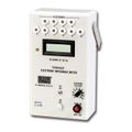
The Grass S88 Impedance Meter measures AC impedance (resistance and capacitance). An impedance check should be performed on all electrodes used for EEG or EMG. When two or more electrodes are plugged into the electrode switch positions, all electrodes except the one selected electrode being measured are connected together and provide the reference for the one being measured.
-
Grass Impedance Meter
-
- 1. The Electrode Selector Switch should be at Jack position 1 or 2.
- 2. Plug the ground electrode (FPz) into electrode Jack 1 position.
- 3. Plug the other electrodes into the Jack (2, 3, 4, etc) positions in a systematic manner one at a time.
- 4. Press the Red ON Button to activate the impedance check. The power will automatically shutoff after approximately 2 minutes. (There is no OFF button.)
- 5. If the impedance is too high - take a cotton tip swab dipped in Nuprep (Abralyt or other skin prep) and twirl against the skin until impedance is at an appropriate level. Then re-insert Elifix electrolyte.
- Impedance Recommendations
EEG Electrodes ≤ 5Kohms EMG/EOG/ECG ≤ 50Kohms
- 6. After checking the impedance of each electrode plug the electrode into the appropriate Electrode Jackbox / Amplifier Position.
*If the electrode impedance exceeds 199.9K ohm, a “1” will appear in the left display window with all other digits blanked out indicating the impedance is too high. Take a cotton swab that has been dipped in Nuprep and insert it through the electrode opening and twirl against the skin. Re-apply electrolyte. Re-check the impedance.
MEG DSQ 3500 Amplifier Setup
Located inside the MSR on the table near the MEG machine. The DSQ 3500 Amplifier has inputs for:
- Fiducial Coils - Nasion, Left Ear, Right Ear, Inion(unused) and Vertex(unused);
- 21 Unipolar Jacks - there are 21 unipolar channels which measure the difference between an electrode and a common reference channel. The reference channel is common to all of the EEG unipolar channels;
- 8 Bipolar Channels - that measure the potential difference between two individual electrodes. These channels are labelled A - G on the jackbox, however, the channels are numbers 56 to 62 in the parameters;
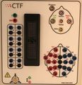
- ZIF Connector/Jig Connector - for the EEG EasyCap System which can accommodate up to 56 electrode positions;
- Ground Jack - Z;
- Reference Jack - Ref.
Please note: There is a Static Dissipation Button which you must touch before touching anything else on the amplifier and before plugging any electrodes into the amplifier.
- If Performing EEG:
- Place cerebral electrodes in the numbered jacks / unipolar channels or plug the EasyCap JIF Connector into the input module on the amplifier.
- Plug FPz into the ground (Z / green) electrode position.
- Plug the both Mastoids into a Linked Electrode Adaptor (Y Connector) then place the single end of the adaptor into the Ref (red) position to link the mastoids together.


