Subject Preparation: Difference between revisions
Moved EEG Instructions |
No edit summary |
||
| Line 87: | Line 87: | ||
*Place tape over the cables to secure. |
*Place tape over the cables to secure. |
||
::::{| class="wikitable" |
|||
|- |
|- |
||
| <gallery> |
| <gallery> |
||
| Line 95: | Line 95: | ||
::::'''Head Coil Locations''' |
|||
::::{| class="wikitable" |
|||
|- |
|- |
||
|'''Right Ear'''||'''Naison'''||'''Left Ear''' |
|'''Right Ear'''||'''Naison'''||'''Left Ear''' |
||
| Line 103: | Line 103: | ||
|} |
|} |
||
''***Color coding system may change; all changes will be posted in the MEG Lab for reference.'' |
|||
<br> |
<br> |
||
==Electroculogram (EOG) Eye Lead Placement== |
|||
'''Used to identify and monitor eye blinks and saccadic eye movements. This is a one channel montage which is designed to pick up horizontal and vertical eye movement from both eyes. There are many ways to monitor eye movements- some montages use one channel and some use two channels. Selection is usually based upon the reason(s) for monitoring the eye movement.''' |
|||
<br> |
|||
*Left Infra Orbital (LIO) - Place electrode on the orbital ridge centered directly under the eye. |
|||
*Left Outer Canthus (LOC) - Place electrode at the lateral junction of the upper and lower eye lid. |
|||
*Clean the skin on the cheek near the eyes and behind the left ear with alcohol and Nuprep Skin Cleaner. Wipe the skin to remove the gritty residue. |
|||
*Attach the Large EEG Adhesive Washers to the electrodes. |
|||
*Place the Infra Orbital electrode. |
|||
*Place the Outer Canthus electrode. |
|||
*Place a ground electrode on forehead or the left mastoid bone behind the ear. |
|||
*Press the electrodes onto skin. |
|||
*Apply Elifix Electrolyte through the electrode opening. |
|||
*Check the impedances using the Grass Impedance Meter. |
|||
*Plug in the left infra orbital electrode in jack# 1 and the left outer Canthus electrode in jack# 2 and the ground into jack# 3. |
|||
*Push the red ON button. |
|||
*The Electrode Selector should be at 1 or 2. |
|||
*EOG impedance should be < 50k ohms. |
|||
*Secure with tape. |
|||
*Refer to section entitled “Electrode Impedance Meter Check” for more detailed information on reducing impedance. |
|||
::::''If you require further assistance, please request technical assistance from MEG staff.'' |
|||
:::::::::::::::::::::::::::::{| class="wikitable" |
|||
|- |
|||
| <gallery> |
|||
Electroculogram_Placement_Picture_2_cropped.jpg|<center>Left Eye One Channel EOG<div> |
|||
</gallery> |
|||
|} |
|||
<br> |
|||
==Reducing Skin Impedances== |
|||
'''Lemon Prep or Nuprep can be used for reducing skin impedance. Both are topical abrasives used to clean the skin to remove any natural or applied oil, lotions and/or dead skin. Remove with water.''' |
|||
*Insert the wooden end of a cotton swab through the opening of the electrode to push hair aside (in one direction) until the skin is clearly visible. |
|||
*If the hair is long, lift up the electrode a little and let it down again while moving back the swab to grab a new bunch of hair (this will prevent the hair from slipping back). |
|||
*Dip the swab into the Nuprep (Abralyt or other skin prep) and insert through the electrode opening. |
|||
*Twirl the swab against the skin using the thumb and index finger. |
|||
:::::::::::::::::::::::::{| class="wikitable" |
|||
|- |
|||
| <gallery> |
|||
NUPREP_Picture.jpg|<center>Nuprep<div> |
|||
Lemon_Prep_Picture_cropped.jpg|<center>Lemon Prep<div> |
|||
</gallery> |
|||
|} |
|||
<br> |
|||
==Applying Electrolyte== |
|||
'''Elifix and Ten/20 Conductive Creams are opaque white, water soluble electrolytes substances used as a conductive and/or fixing/adhering mediums to attach electrodes. Removed with warm water.''' |
|||
::'''*If using Elifix or Abralyt''' - fill a syringe with the cream. |
|||
::::- Squirt into the middle of each electrode opening. |
|||
::'''*If using Ten/20''' - scoop paste into a cup electrode (this paste is too thick to squirt from a syringe). |
|||
::::- Press firmly on the skin. |
|||
::'''*Completely fill the electrode space (the space from the skin to the electrode) with cream / paste so that there are no air pockets and the electrolyte makes good contact with the skin. |
|||
::::::::::::::::::::::::::::{| class="wikitable" |
|||
|- |
|||
| <gallery> |
|||
Ten_20_Paste_Picture1.png.jpg|Ten/20 Conductive Paste |
|||
</gallery> |
|||
|} |
|||
''If the electrodes are closely spaced, when using Elifix or Abralyt, in order to prevent "electrode bridging" draw back the syringe concurrently to prevent electrolyte from swelling underneath the electrode rim and bridging to the adjacent electrodes. When using Ten/20 do not allow the paste from adjacent electrodes to touch'' |
|||
<br> |
|||
==Electrode Impedance Meter Check== |
|||
'''The Grass S88 Impedance Meter measures AC impedance (resistance and capacitance). An impedance check should be performed on all electrodes used for EEG or EMG. When two or more electrodes are plugged into the electrode switch positions, all electrodes except the one selected electrode being measured are connected together and provide the reference for the one being measured.''' |
|||
::::{| class="wikitable" |
|||
|- |
|||
| <gallery> |
|||
Grass_Impedance_Meter.jpg|'''Grass Impedance Meter''' |
|||
</gallery> |
|||
|} |
|||
::1. The Electrode Selector Switch should be at Jack position 1 or 2. |
|||
::2. Plug the ground electrode (FPz) into electrode Jack 1 position. |
|||
::3. Plug the other electrodes into the Jack (2, 3, 4, etc) positions in a systematic manner one at a time. |
|||
::4. Press the Red ON Button to activate the impedance check. The power will automatically shutoff after approximately 2 minutes. (There is no OFF button.) |
|||
::5. If the impedance is too high - take a cotton tip swab dipped in Nuprep (Abralyt or other skin prep) and twirl against the skin until impedance is at an appropriate level. Then re-insert Elifix electrolyte. |
|||
:::::::::::::::::::::::::::'''Impedance Recommendations''' |
|||
:::::::::::::::::::::::::::{| class="wikitable" |
|||
|- |
|||
| '''EEG Electrodes''' || '''≤ 5Kohms''' |
|||
|- |
|||
| '''EMG/EOG/ECG''' || '''≤ 50Kohms''' |
|||
|} |
|||
::6. After checking the impedance of each electrode plug the electrode into the appropriate Electrode Jackbox / Amplifier Position. |
|||
''*If the electrode impedance exceeds 199.9K ohm, a “1” will appear in the left display window with all other digits blanked out indicating the impedance is too high. Take a cotton swab that has been dipped in Nuprep and insert it through the electrode opening and twirl against the skin. Re-apply electrolyte. Re-check the impedance.'' |
|||
<br> |
|||
==MEG DSQ 3500 Amplifier Setup== |
|||
'''Located inside the MSR on the table near the MEG machine. The DSQ 3500 Amplifier has inputs for:''' |
|||
:::::::::::::::::::::::::::{| class="wikitable" |
|||
|- |
|||
| <gallery> |
|||
MEG DSQ 3500 Amplifier.jpg |
|||
</gallery> |
|||
|} |
|||
::*'''Fiducial Coils''' - Nasion, Left Ear, Right Ear, Inion(unused) and Vertex(unused); |
|||
::*'''21 Unipolar Jacks''' - there are 21 unipolar channels which measure the difference between an electrode and a common reference channel. The reference channel is common to all of the EEG unipolar channels; |
|||
::*'''8 Bipolar Channels''' - that measure the potential difference between two individual electrodes. These channels are labelled A - G on the jackbox, however, the channels are numbers 56 to 62 in the parameters; |
|||
::*'''ZIF Connector/Jig Connector''' - for the EEG EasyCap System which can accommodate up to 56 electrode positions; |
|||
::*'''Ground Jack''' - Z; |
|||
::*'''Reference Jack''' - Ref. |
|||
'''''Please note: There is a Static Dissipation Button which you must touch before touching anything else on the amplifier and before plugging any electrodes into the amplifier'''''. |
|||
::'''If Using a One Channel Bipolar EOG:''' |
|||
::Plug the electrodes into a bipolar channel. |
|||
::::::::::::::::::{| class="wikitable" |
|||
|- |
|||
! EOG ELECTRODE !! Location !! Bipolar Channel 56 |
|||
(Channel 56 is the first Bipolar Channel on the Amplifier) |
|||
|- |
|||
| '''Lt OC''' || Left Outer Canthus || Channel-056 A+ (black) |
|||
|- |
|||
| '''Lt IO''' || Left Infra Orbital || Channel-056 A- (blue) |
|||
|} |
|||
:::::::''Note: if recording only EOG (no EEG) you will still need to have a ground electrode.'' |
|||
Revision as of 13:55, 16 December 2021
Subject Preparation: De-metaling
Before entering the MSR (Magnetically Shielded Room) subjects must remove any metal from their person.
There are no known risks associated with MEG recordings. Although wearing metal objects while in the MSR is not harmful to the individual, bringing metallic or magnetic objects into the MSR causes interference and high noise levels in the recording. *It is recommended that subject are screened and given instructions before arriving for testing. However, if subjects arrive with metal on their clothing that can not be easily removed, they must change into scrubs, which are available for all participants in the NMR Center changing room.
Please use the MEG Screening Questionnaire when scheduling participants.
- Subjects must remove:
- -Bras with metal underwires, clasps or hooks.
- Note: Some sports bras may have powder coated metal connections which look and feel like plastic. You can use the metal scanner in the NMR Center changing room to check any questionable elements.
- -Makeup - mascara, eye liner, eye shadow
- -Clothing containing metallic shiny threads or glitter
- -Metal on clothing i.e., metal buttons, snaps or trimming
- -Belts
- -Keys
- -Watches
- -Rings or other jewelry
- -Coins
- -Eyeglasses
- -Cell phones
- -Pagers
- -Credit Cards
- -Small metal objects such as hair pins, paper clips, safety pins, etc.
- Additionally, everyone entering the MSR must also remove their shoes or use protective booties to prevent magnetic dust from getting into the MSR.
Head Size / Fit Test
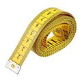
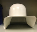
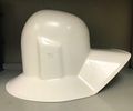
Use a tape measure and / or the mock MEG helmet to determine whether: a) the subject will fit the MEG sensor helmet/dewar; b) how much padding is needed to fill the excess space to prevent head movement and c) how high up in the dewar helmet the subject can be raised for optimal placement. The helmet/dewar will fit subjects up to about 59cm head circumference (within 98 percentile for head size).
- Determine the subject's head size by measuring the:
- - Head Circumference,
- - Nasion-Inion Distance and
- - Preauricular Point to Preauricular Point Distance.
Head Size Gantry Limits Nasion-Inion Preauricular Circumference MEG / EEG ≤ 40cm ≤ 40cm ≤ 59cm
-
Tape Measure
-
- *Note or record measurements.
- Determine how the subject will "fit" inside the dewar helmet:
- – Place the MEG "sizing" helmet along with a protective cap over the subject's head.
- • Note the fit; if the helmet does not fit (with the coils on and inside the helmet) then the subject is not a good candidate for MEG; if the subject fits then note the amount of space the subject has to move his/her head.
- – Insert Pearltec Head Positioning pads to restrict head movement then re-try the helmet. Please instruct the participant to inflate the positioning pads. Note: you want the helmet to be tight enough to restrict head movement but not so tight as to cause a headache.
- – Place the MEG "sizing" helmet along with a protective cap over the subject's head.
- Determine how to place the subject's head properly - at the top the dewar helmet.
- • Note how far down over the head the helmet comes as this will give you a general idea of how high up in the dewar the subject can go in order to position the subject's head at the top of the dewar (closest to the sensors at the top of the helmet) without covering the subject's eyes.
-
MEG Sizing Helmet-front
-
MEG Sizing Helmet-side
-
Fiducial Points / Head Coil Placements
Used for head localization (the process of locating the subject’s head in space relative to the Dewar). Used later to co-register the MRI Coordinate System with the MEG Head Coordinate System.
- Place a small black dot at 1.5cm up from the nasion (indentation between the forehead and the nose) midline. *The dot may be placed slightly higher if the nasion curvature is such that it does not allow level placement of the head coil.
- Place a small black dot below the left & right preauricular points centered at 1.5cm in front of the tragus. Measure for accuracy.
- Take a picture of these locations using the HP 715 Digital Camera. Download and print the pictures.
- Attach Small (MEG) Adhesive Washers to head localization coils.
- Attach head localization coils at the fiducial marks.
- Make sure the marks line up with the center of the head coils.
- Place tape over the cables to secure.
-
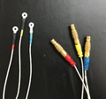
MEG Fiducial Head Coils
-
- Head Coil Locations
Right Ear Naison Left Ear Red Yellow Blue
***Color coding system may change; all changes will be posted in the MEG Lab for reference.


